
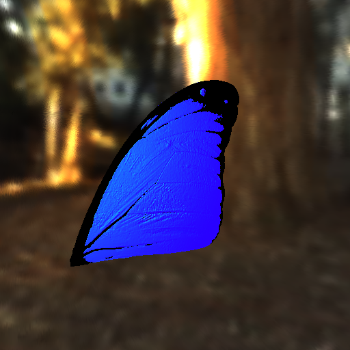
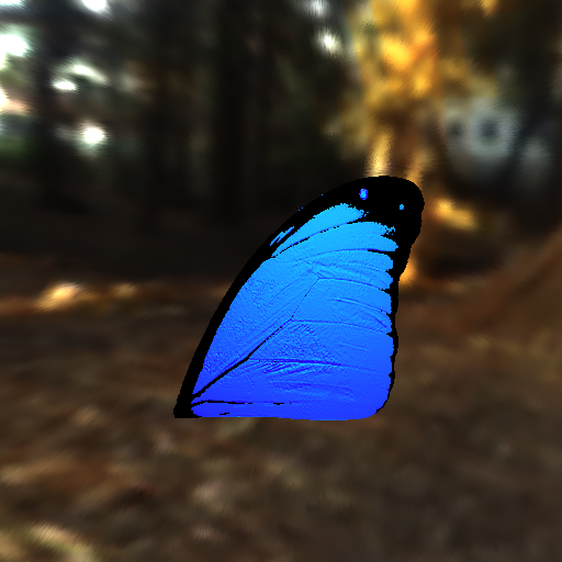
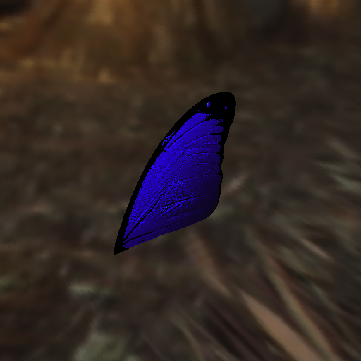
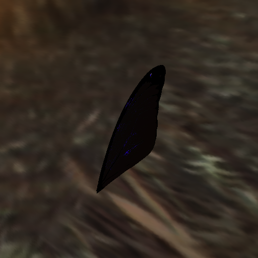
You can either click on thumbnails to download avi format movies.


Iridescence Anisotropic Morpho Butterfly - Anisotropic Only Morpho Butterfly!
Or, you can watch a lower resolution version on youtube:
Click each image to see the full resolution version.
A Physically Based Anisotropic Iridescence Model for Rendering Morpho Butterflies Photo-realistically
Rendering the brilliant iridescent colors of the Morpho butterflies has been a challenge in computer graphics. The cause of vivid blue color of the wings of these species is not as the result of the pigments of the wing. They are caused by the physical microscopic structures on the scales of the wing. These micro-structures has been studied extensively in various fields by different expertise [Yinlong Sun . 2006] [FOX, D. 1976] [VUKUSIC, P. AND SAMBLES, R.2003].
In this project I have addressed the problem of rendering the anisotropic iridescence colors of the Morpho butterflies photorealistically. The developed model is physically based and combines two previously presented models; Multi-layer thin film model [Yinlong Sun . 2006] and separate lamellae model [S.KINOSHITA et al. 2002]. Both of those models fail to describe the anisotropic nature of the light reflectance on these structures. The introduced model in this paper produces an anisotropic model with interpolating between those two isotropic models. The model is based on the physical properties and analytical derivations of the microscopic structures of on the scales of the wings.
Rendered images with this model match the experimental description [Fox 1976; Simon 1971] of iridescence properties of the Morpho butterflies.
Keywords: Morpho butterfly, iridescence, interference, photorealistic rendering, physically based model
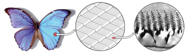
Figure 2: Photograph of a Morpho butterfly [scale:13 cm]
(left), the scales on its wings [scale:0.1 mm]
(center), and an electron microscope image of the micro-structures of ridges of wings [scale:200 nm]
(right). [Yinlong Sun 2006] [Vukusic and Sambles 2003]
The wings of male Morpho butterflies demonstrate iridescent colors which varies from cyan to blue and violet, with increase of the lighting or viewing angle [Fox 1976; Simon 1971]. Also, under some conditions the iridescence of a Morpho butterfly disappears for example by increasing the viewing angle [Fox 1976; Vukusic et al. 2001a].
According to studies by electron microscopes the ridges extend into the air in multiple layers and film thickness and air thickness are almost the same about 90 nm [Nassau 1983]. The refractive index of the solid material of the wings is 1.56 [Vukusic et al. 1999]. When the light interacts with the ridges, multiple rays reflect from the film surfaces. These rays interfere with each other and make the iridescence color which is amplified in some wave lengths and attenuated in some other wave lengths. The number of layers for the Morpho butterfly is around 10 in average. The studies with an electron microscope [Vukusic and Sambles 2003] show that the spatial distribution of lamellar ridges are to be periodic. The lamination of the ridges can be simulated as a perfectly periodic multi-layer plus some random fluctuations in the layer thicknesses. These random factors will make the interference spectra broader and result in less saturated colors. This simple model also applies to many other iridescent animals such as ground beetles [Yinlong Sun . 2006] [Fox 1976; Simon 1971].
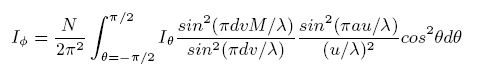
The model presented in this paper is very similar to the model in [S.Iwasawa et al. 2004]. There are some differences which I will explain later in in section 6.2. In that paper they have considered two perpendicular directions on the wings of butterflies. One along the direction of the ridges and one perpendicular to the other one. If the light intersect with the wings perpendicular to the direction of ridges the appropriate model would be Separate Lamellae described in [S.KINOSHITA et al. 2002]. In contrast, if the light intersect with the wing along the ridges the appropriate model would be the multi-layer thin film described in [Yinlong Sun . 2006] [J.Gonzato et al. 2003]. At the end we interpolate between the results of these two models for any given direction to approximately simulate the anisotropic iridescence appearance of the butterfly wings.
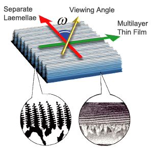
Figure 3: Combining two different models to get the anisotropic iridescence effect for the wings of the butterfly.
(red) If the light intersect with the wings perpendicular to the direction of ridges the appropriate model would be Separate Lamellae.
(green) If the light intersect with the wing along the ridges the appropriate model would be the multi-layer thin film.
(yellow) We can interpolate between the results of these two models for any given direction to simulate the appearance of these micro-structures. [S.Iwasawa et al. 2004].
For using both described models one has to calculate the spectral reflectance of light on each point on the wings of the butterfly. In current implementation of reflectance intensities are calculated in the range of 380nm to 740nm range, every 5nm apart. In order to calculate the intensity of incidence light, I used CIE standard illumination D65 in all the incoming directions (Simulation of outdoor environment during the day). Then the spectral intensities are converted to their corresponding XY Z values using CIE1931 matching curves and at the end XY Z values are converted to the RGB using standard NTSC conversion matrix. Note that here it is not necessary to have a rendering engine which supports full spectrum rendering. One only needs to convert the incident light from RGB to full spectrum and after calculating the reflected light spectrum convert it to RGB. However, I have ignored the first part for incident light and always assumed that the incident light is standard D65.
For simulating the multi-layer thin film properties of the wings I used the approximation of equation 8 derived in [Yinlong Sun 2006] since it is simpler and closely matches the exact curves. The approximation formula is stated as:
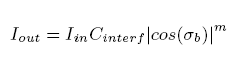
if cos(sigma_b) > 0 and 0 Otherwise where sigma_b is defined as before:
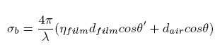
Refer to [Yinlong Sun . 2006] for more explanations of this approximation equation. In order to simulate the multi-layer thin film appearance I had to calculate the equation 8 for all diffract wavelengths near the visible spectrum and cumulate the results and convert them to XY X. And at the end convert the resulted XY Z value to RGB triplet and display them. Figure 7 shows a butterfly rendered solely with the multi-layer thin film model.
As I mentioned in section 4.1.2 the proposed reflectance model is both view direction dependent and light direction dependent. But in order to interpolate between two diffract reflectance function they should have the same dimensionality. Therefore, I had to either make the multi-layer thin film model light direction dependent or make the separate lamellae model light direction independent. I chose the latter approach by integrating the equation 4 over all the incoming directions for the light.
In other words for any given view direction theta I have to calculate the following integral:
However, integration the equation 4 analytically is very difficult and because of complex nested sin functions even commercial mathematical softwares refused to find the analytic solution to the integral. I solved this integral numerically by sampling the light direction in every degree. Note that this integral should be evaluated for all diffract wave-lengths as well. Therefore, this step is computationally expensive and solving the integration analytically would speed up this step dramatically. Image to the right of figure 7 shows a butterfly rendered solely with the separate lamellae model.
All the models used in this paper are modeled by the author using Maya. The Modeling process was based on a photograph of the a Morpho butterfly taken from the Society of Structural Color’s webpage (http://mph.fbs.osaka-u.ac.jp/ ssc/). The model also includes bump-maps, iridescence-maps, direction-maps and texture-bitmaps for the back of wings (see figure 6). All the texture-maps are also generated from the base photograph. Bump-maps are used to perturb the normals and were essential in giving the butterfly a photorealistic look. Iridescence-maps are used to determine the material of the surface and determine whether the iridescence shader should be used or not. Direction-maps will provide the direction of ridges on the wings and are essential for the anisotropic simulation of the wings. Figure 6 shows the model and all these texture-maps together.
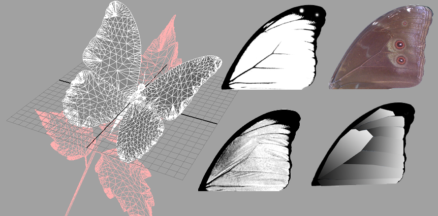
Figure 6: Modeling geometry and textures for the scene.
(left) 3D geometry model in the construction process in Maya.
(center-top) Iridescence map which determines which shader function will be used for shading the geometry.
(center-bottom) Bump-map used for perturbing normals on the surface of the wings.
(right-top) Texture-map for the back of the wings.
(right-bottom) Direction-map which provides the direction of the ridges and is used for interpolating between the two diffract models.
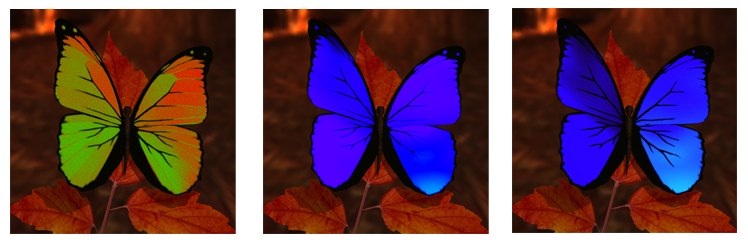
Figure 7: Anisotropic properties of the iridescence shading model.
(left) The result of separate lamellae model is colored red and the multilayer thin film results are colored green for illustration of the interpolation behavior. The amount of contribution of each model depends on the viewing angle and the direction of ridges on the wing.
(center) Butterfly is rendered using only the multi-layer thin film.
(right) Butterfly is rendered using only the separate lamellae model. Final image would be the combination of these two models.
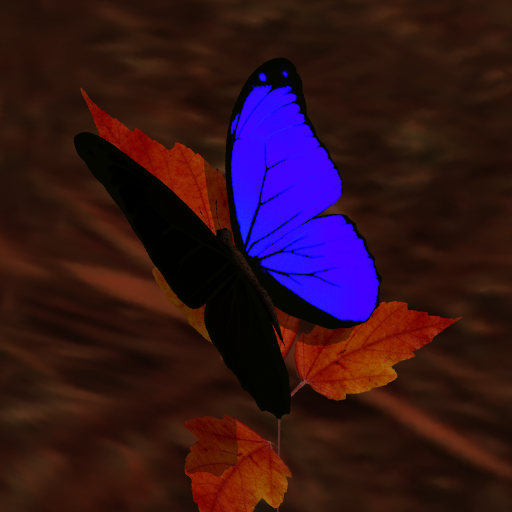
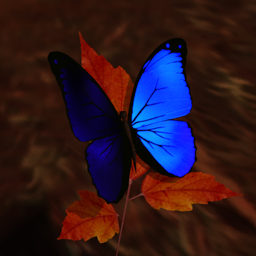
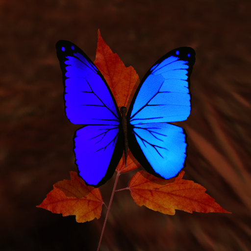
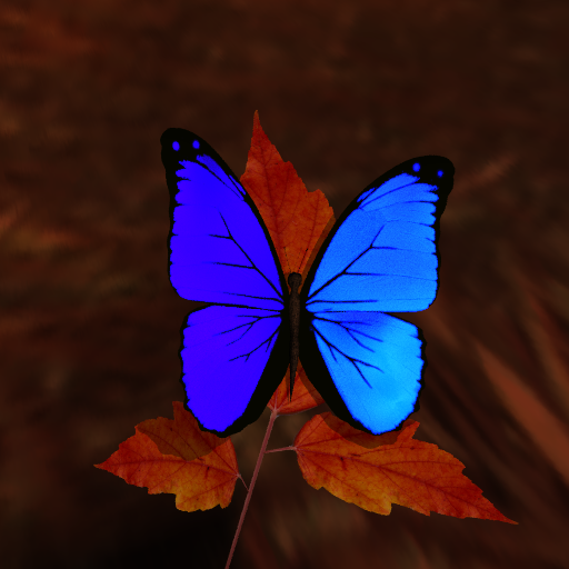
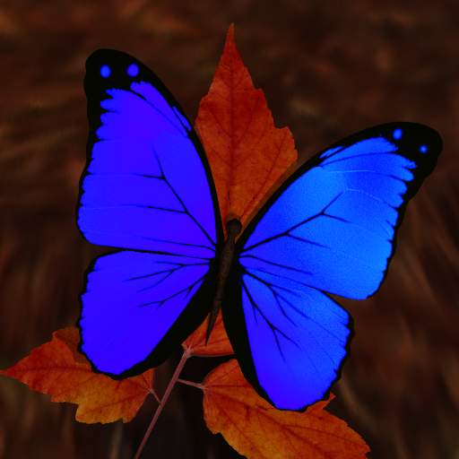
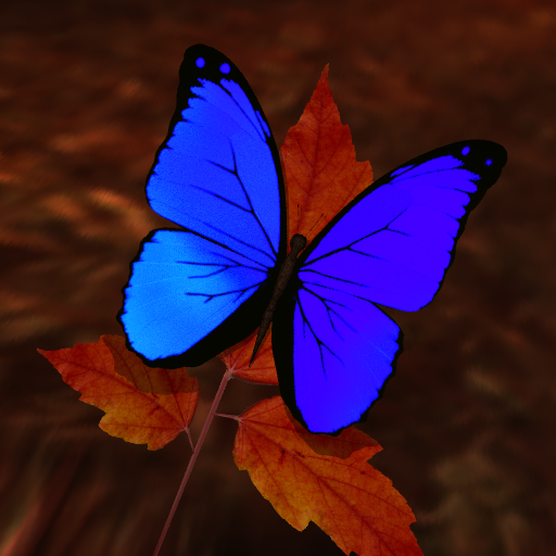
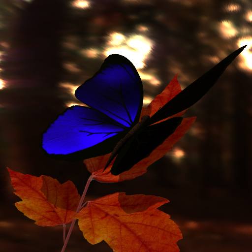
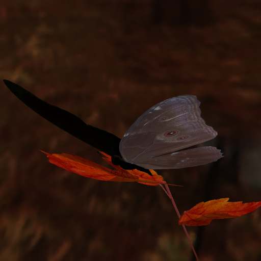
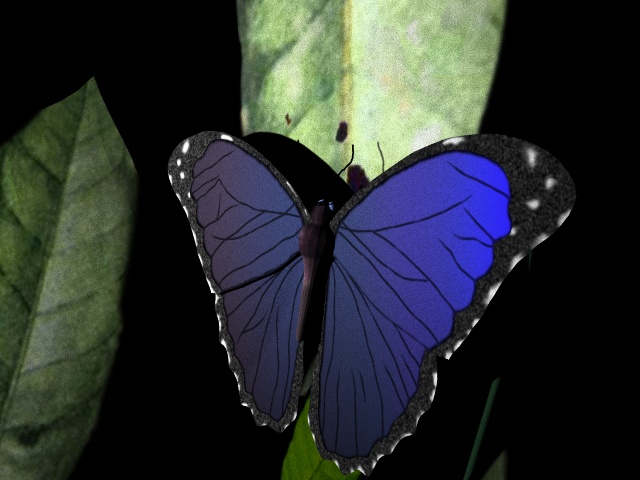
Rendered Images Figures 1 8 and 9 show some rendered images of the Morpho butterfly from different viewing directions. The shading model is independent of the direction of the light and assumes the light reaches the surface from all the direction by the spectrum distribution according to standard CIED65. Figure 8 (right) best shows the anisotropic behavior of the model where the direction of the ridges change between the regions of the wing. The sophisticated geometry model, bump- mapping, iridescence-mapping and directionmapping (see figure 6) have added a lot to the realism of the results. Figure 1 shows some snapshots of a movie which is available on the author’s web-page. (http://graphics.ucsd.edu/ iman) This movie perfectly shows the behavior of the developed iridescence shading model.


I have developed an iridescent anisotropic shading model for rendering Morpho butterflies photo-realisticly. Rendered images match the experimental descriptions of the iridescent properties of Morpho butterfly [Fox 1976; Vukusic et al. 2001a; Simon 1971].
The developed anisotropic model is archived by combining two diffract isotropic models and applying them in two different directions. These directions presents the orientation of the underlying microscopic structures. For the future work I will compare my rendered images with the appearance of a real butterfly. Also, I plan to come up with an analytic solution for the integration in the separate lamellae model which is currently calculated numerically and is very slow and computationally expensive. Also, one can consider the shape of the lamellae on the wing and the fact that at the top they are narrower than at their bottom. This may lead to a new and more accurate model.
You can also compare my results with a similar project which has won the Grand Prize of Stanford's Rendering Completion at 2001.
Grand Prize of Stanford's 2001 Rendering Competition
Simulating Interference effects in LRT: Iridescence in biological structures
By Steve Bennett and Arthur Amezcua
They also had a generated movie from their model.
SHUN IWASAWA, NAOHIRO SHICHIJO, YOICHIRO KAWAGUCHI 2004. VRendering Methods for ModelsWith Complicated Micro Structures
YINLONG SUN 2006. Rendering Biological Iridescences with RGB-Based Renderers
SHUICHI KINOSHITA, SHINYA YOSHIOKA, YASUHIRO FUJII, NAOKO OKAMOTO 2002. Photophysics of Structural Color in the Morpho Butterflies
J.-C. GONZATO, B. PONT 2003. A phenomenological representation of iridescent colors in butterfly wings
ISHIGURO, K., IKEDA, H., YOKOTA, E. 1985. Nature of Multilayer Film. Optical Thin Film. Optical Technique Series Vol.11,Fujiwara, S., Kyoritsu Shuppan co., ltd., 25-30.
FOX, D. L. 1976. Animal Biochromes and Structural Colours. University of California Press, Berkeley, CA
SIMON, H. 1971. The Splendor of Iridescence of Structural Colors in the AnimalWorld. Dodd, Mead Company, New York, NY.
LEE, D. W. 1991. Ultrastructural basis and function of iridescent blue color of fruits in Elaeocarpus. Nature 349, 260262.
LEE, D. W. 1997. Iridescent blue plants. Amer. Scient. 85, 5663.
VUKUSIC, P. AND SAMBLES, R. 2003. Photonic structure in biology. Nature 424, 852855.
VERITY, E. 1980. Color Observed. Van Nostrand Reinhold, New York, NY.
JUDD, D. B. AND WYSZECKI, G. 1975. Color in Business, Science and Industry. John Wiley Sons, New York, NY.
FOX, D. L 1979. Biochromy: Natural Coloration of Living Things. University of California Press, Berkeley, CA.
TABATA, H., KUMAZAWA, K., FUNAKAWA, M., TAKIMOTO, J., AND AKIMOTO, M. 1996. Microstructures and optical properties of scales of butterfly wings. Opt. Rev. 3, 129145.
VUKUSIC, P., SAMBLES, R., LAWRENCE, C., AND WAKELY, G. 2001b. Sculpted-multilayer optical effects in two species of Papilio butterfly. Appl. Opt. 40, 11161125.
NASSAU, K. 1983. The Physics and Chemistry of Color: The Fifteen Causes of Color. John Wiley Sons, New York, NY.
VUKUSIC, P., SAMBLES, J. R., LAWRENCE, C. R., AND WOOTTON, R. J 1999. Quantified interference and diffraction in single Morpho butterfly scales. Proc. R. Soc. London Ser. B266, 14031411.
ANDERSON, T. F. AND RICHARDS, A. G. 1942 . An electron microscope study of some structural colors in insects. J. Appl. Phys. 13, 748758.
GHIRADELLA, H. T. 1991. Light and color on the wing: Structural colors in butterflies and moths. Appl. Opt. 30, 34923500.
FRED ALMGREN, JOHN M. SULLIVAN 1993. Visualization of Soap Bubble Geometries. In M. Emmer, editor, The Visual Mind (MIT Press, 1993), 79-83
EIHACHIRO NAKAMAE, KAZUFUMI KANEDA, TAKASHI OKAMOTO, AND TOMOYUKI NISHITA 1990. A Lighting Model Aiming at Drive Simulators. ACM Computer Graphics (SIGGRAPH 90), 395-404
JAY S. GONDEK, GARY W. MEYER, JONATHAN G.NEWMAN 1994. Wavelength Dependent Reflectance Functions. ACM Computer Graphics (SIGGRAPH 94), 213-220 395-404
NISHITA, T., DOBASHI, Y., KANEDA, K. AND YAMASHITA, H. 1996. Display method of the sky color taking into account multiple scattering. Pacific Graphics 96, 117-132
A.J. PREETHAM, PETER SHIRLEY, BRIAN SMITS 1999. A Practical Analytic Model for Daylight. ACM Computer Graphics (SIGGRAPH 99), 91-100
N. NAGATA, T. DOBASHI, Y. MANABE, T. USAMI, AND S. INOKUCHI 1997. Modeling and Visualization for a Pearl-Quality Evaluation Simulator. IEEE Trans. Visualization and Computer Graphics(1997), Vol. 3, No. 4, pp. 307-315
JOS STAM 1997. Diffraction Shaders. ACM Computer Graphics (SIGGRAPH 99), 101-110
